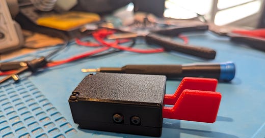
In the spirit of my previous post where I encouraged my readers to support the small creators in our community, I recently decided to purchase a new Morse paddle from Jonathan KM4CFT, which I learned about from K4SWL’s excellent blog qrper.com. I noticed that Thomas wrote:
Jonathan told me that he’s using the kit as a bit of a fund-raiser for a much more ambitious project he has in the works.
I’ve talked to Jonathan a bit over email about some technical topics, so I definitely wanted to encourage him further, plus I actually have been on the lookout to add to my paddle collection, especially the type of paddles that are smaller and would work well for ultra portable QRP ops, so this fit the bill nicely.
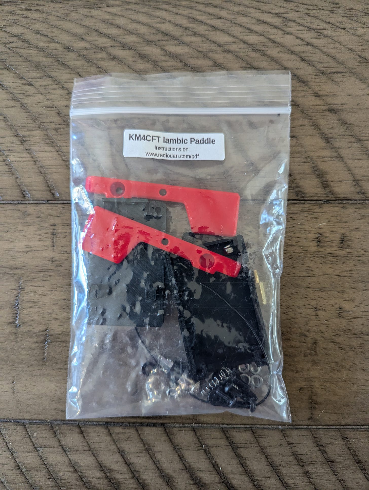
I ordered the paddles with red finger pieces from W7RF’s ebay shop, and it didn’t take long for the package to arrive here from Colorado. The kit came packaged in a clear plastic resealable bag, as many kits from small independent creators often do. The link to the build instructions are right on the label, so no worries on getting right to the build.
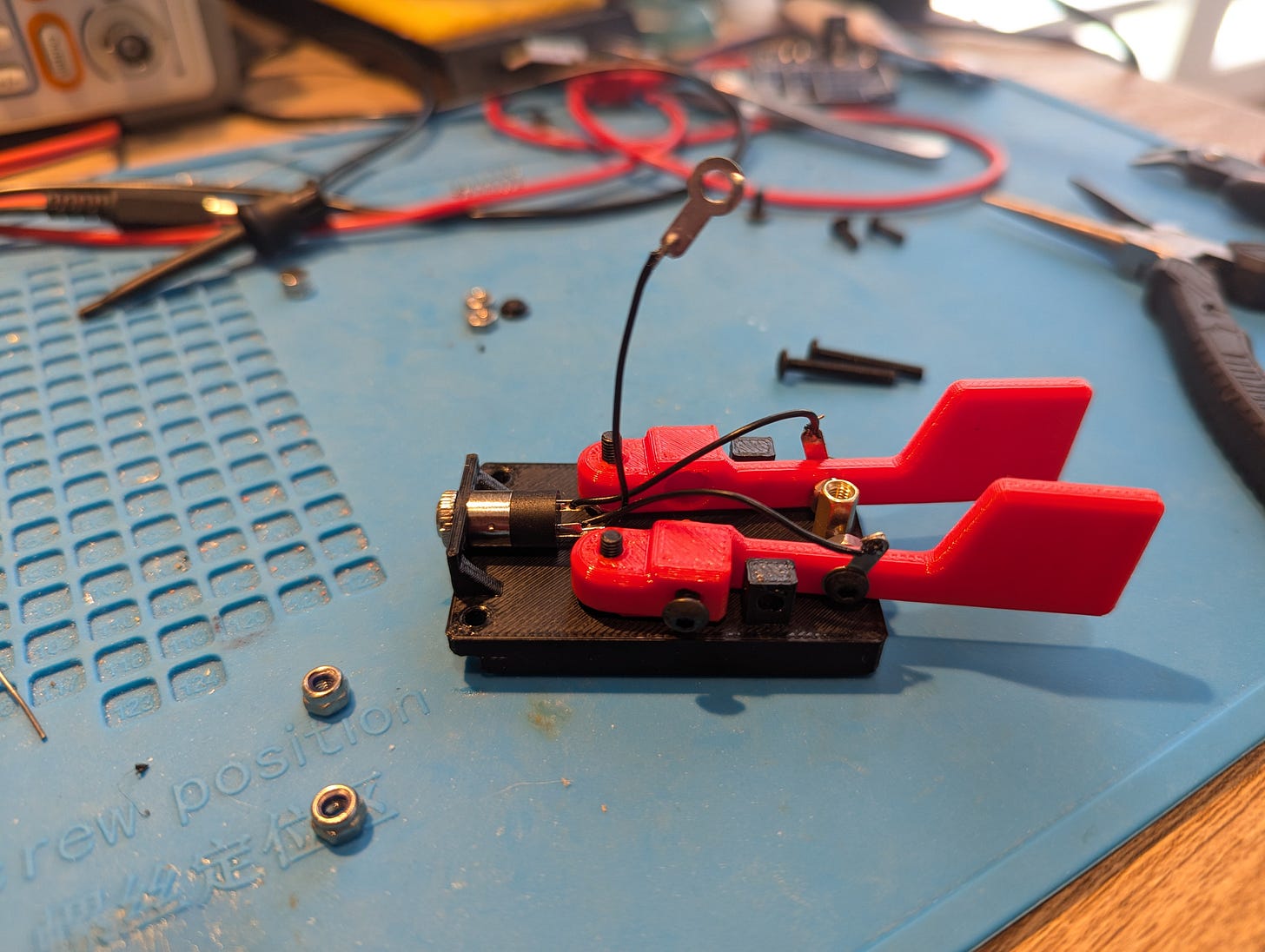
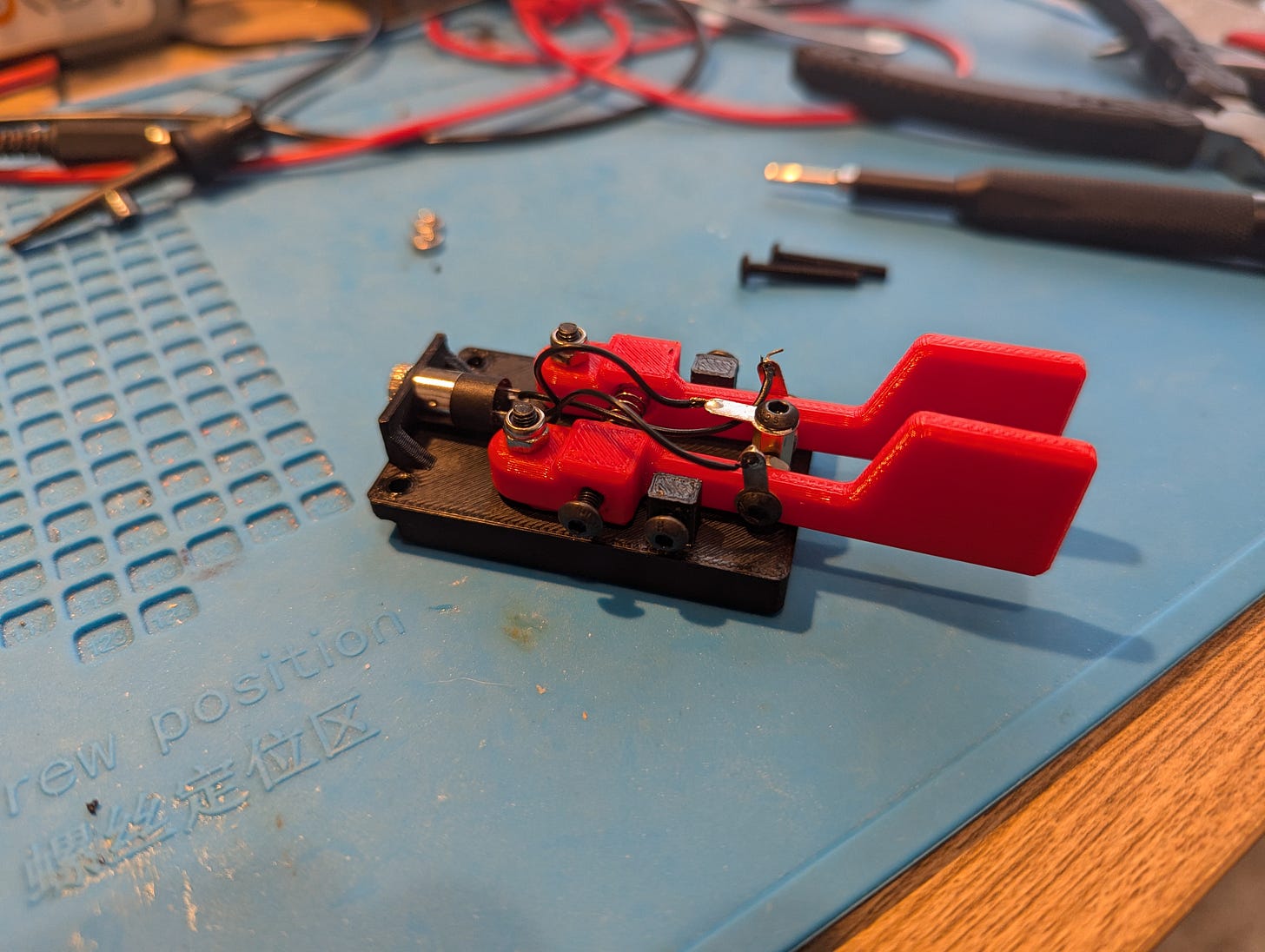
The 3D printed parts are all printed in PETG, so they should be more durable and heat-resistant than a PLA print would be. The assembly is straightforward and well-explained in the documentation. I would not rate this a beginner kit, but should easily be doable by someone with a bit of mechanical assembly and soldering experience. It took me about 30 minutes to put it all together, and I didn’t encounter any major hiccups when building it.
I like the way how the 3.5 mm jack is connected to the three contacts via ring terminals which are soldered. The layout of the 3.5 mm jack also ensures that the wiring of the terminals on the jack are lined up nicely with where the corresponding wire will go. Overall a well thought out design.
The finished paddle is indeed very lightweight and compact. It’s not so tiny that I can’t use it, but I have fairly large hands and I don’t think I could reasonably handle a paddle any smaller, so this design hits the mark for a good balance between portability and usability in my book. Here’s me trying the key out on the bench to get a feel for how it works:
Nice! However, I knew that the real test would be to use it to make a POTA activation, so when my schedule cleared and the temperature wasn’t ridiculously hot, I decided to get out to Maud Williamson State Recreation Site, the nearest POTA park to my house, for a relatively quick activation using the KM4CFT paddle.
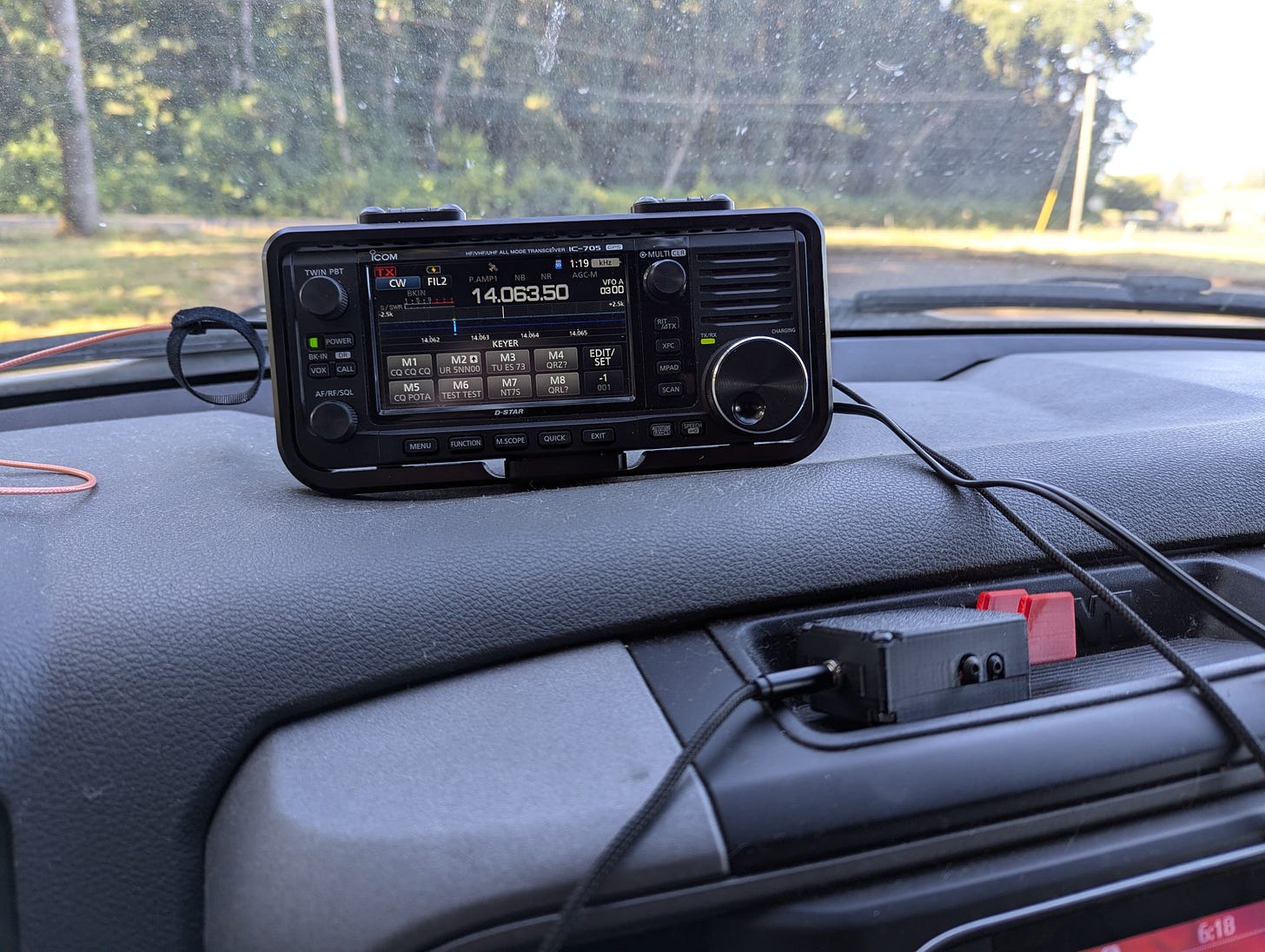
I ended up setting up my Gabil loaded vertical antenna close to my vehicle and operating from the driver’s seat with the A/C on! I only spent about a half hour on the activation, all on 20 meters in the evening, but I logged contacts all around the US. The paddles worked well with the only exception that I fouled up a few times while holding the paddle too close to the front and accidentally mashing in the tension screw, which pushed on the left paddle arm. Oops. I don’t see that as a flaw of the paddle, since it is meant to be very small and portable. I eventually learned to choke up on my grip on the paddle and I was fine after that. I think this paddle would really shine when taking advantage of the magnets on the base, but I didn’t have anything readily available for that kind of mount.
Overall, I think Jonathan did a fine job for the type of paddle this is meant to be. It really will be perfect for the very small ultra portable CW QRP transceiver pack that I’d like to build in the near future.
If you’re interested in ordering your own set of Jonathan’s paddles, here is the link to the eBay page of W7RF, who is the authorized seller.
What’s Next
I’m on the lookout for more creators in our community to support and highlight, so let me know if you have any other recommendations in the comments!
Earlier in the week, I got my big shipment of PCBs from JLCPCB and I’ve been starting to work on building them up so I can validate them. The next post will have a lot more detail, but so far things are looking good. I’ve started working on assembling a Front Panel board and so far all of the things that I’ve fixed on the digital side are working correctly, but I still need to build up the audio section as well. Also, the Si5351A Breakout Boards that I had assembled are looking good and preliminary are working as they should. The main thing I need to do there is get out my old test rig for that board so that I can validate that they pass the tests and can be calibrated. More news on this front soon!

