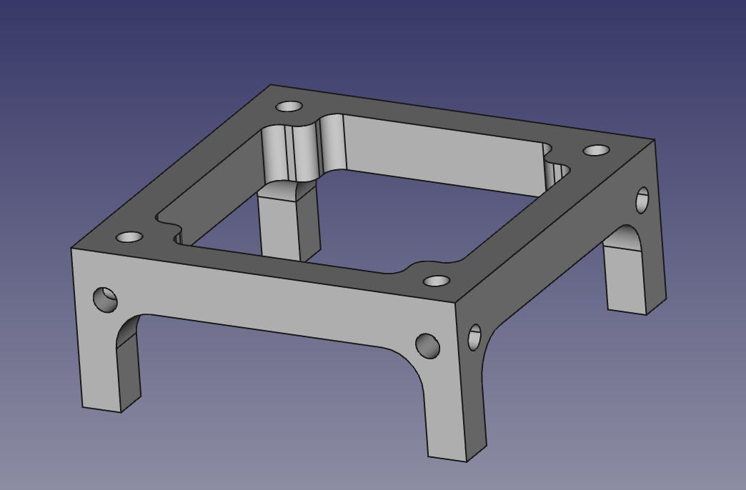
I’ve been working hard over the last few days to level up my FreeCAD skills in order to create an initial design for the Project Yamhill backplane. I’m still a relative noob at 3D CAD, and FreeCAD is a bit quirky, so I definitely had some growing pains, but believe that I have a decent first-pass design of the backplane to work with.
Constraints
Being a tiny operation, getting something injection molded is right out. I also would like this project to be able to be replicated by as many DIYers as possible, so the obvious solution for mechanical design is something which can be 3D printed on a consumer-grade FDM printer. Given the typical X-Y print size of a consumer-grade printer (usually a bit over 200 mm in each dimension), this backplane will have to be modular, and assembled by the end user, into the full-sized chassis.
Also, 3D printers can be notoriously fussy at times, so simplicity in design is an important factor. In order to make printing easier for both manufacturing and a 3D printing novice DIYer, I don’t want to have any overhangs or other features that would require supports or rafts.
Design
Let me start off with the caveat that I Am Not A Mechanical Engineer. It’s possible I’ve made some boneheaded design decisions. Constructive criticism is welcome if you happen to spot such. Please comment below.
The basis of the backplane is what I’m calling a backplane block. This is the sub-unit upon which the main part of the backplane is based. It has a length and width of 50 mm, and is 20 mm tall. There are four M3 screw mounting holes in the corners spaced at 5 mm from the nearest edges. PCBs will be sized to fit within a single block, or multiple if necessary (although there probably won’t be much that needs the space of more than two adjacent blocks). Additional M3 mounting holes are available on the outside vertical faces for attaching other mechanical assemblies.
The array of backplane blocks will be interspersed with channels measuring 10 mm x 10 mm x 50 mm. These will give spacing to the block modules and provide a place to route signal and power wiring.
The backplane blocks are arranged in a 3 x 3 array, with channels placed internally between each block. A support lip is added to the exterior edges of the blocks on two of the sides for use in attaching sections to adjoining sections, as well as for attaching connector PCBs on the rear of the backplane. This is the basic printable part of the backplane, as it measures 180 mm in both the X and Y axes.
Additional support members are available for a couple of different purposes. These supports have holes for M3 screws so that they can be secured to the outside faces of a backplane block. These are spaced so that the lip on the outside edge of the printable section above will sit on top of this support and will allow fastening vertically through both the lip and support with an M3 screw. They are also used on the front of the backplane to provide a support for the front panel, when used with the L-bracket shown below.
This bracket is designed to connect a front panel to the backplane supports fastened to the front face backplane. Please see the top image for details on how this will work.
The dimensions of the entire assembled backplane is 360 mm x 360 mm, not including the front panel and any connector PCBs attached to the rear. It has a 6 x 6 array of backplane blocks, which should be sufficient for the different radio experiments envisioned for this project.
I’ll be getting my 3D printer out of storage and setting up soon so I can start printing these and see how they work in practice. Stay tuned for updates on that front.
Up Next
The next thing to tackle will be power supply board. At first I thought I might make it a special case PCB, designed for a specially-designed place on the backplane, but that makes for more specialized parts to print, which I think is the wrong direction to take things. Therefore, the PSU will most likely be a standard sized 1x2 block PCB.
Decisions
Now that I’m getting onto actual circuit design, I need to make a decision about the connectors and wiring used for board interconnects. I figure that bog-standard 0.1 inch pin headers on the PCB along with M-M jumper wire assemblies will do the trick just fine, but I’m open to other suggestions. More critical are the RF interconnects. Ideally I’d like to find relatively inexpensive top-mounted connectors that have pre-made cable assemblies available in a wide variety of lengths. I’ll be hitting up DigiKey and Mouser to do research, but any pointers on what might be a good choice would be greatly appreciated. Hit the comments section below!


This is a cool project - looking forward to seeing some of the electronics.
Nice progress in just a few days!