


Project Yamhill Front Panel Circuit
The heart of the project

Thanks for your patience for this next bit of content, and thanks for sticking with me! Between all of the scrambling that I had to do to complete our house (as mentioned in the last post) and relatively large complexity of this circuit compared to all of the other blocks to be made, this one was always destined to take a while, but unfortunately it took longer than I expected.
Typically I have been presenting the circuit and the PCB design together in a post, but there’s enough content here in showing off this circuit that it will easily make for a post all by itself. Plus it gives me some more time to work on the PCB layout. I’ve spec’ed most of the components on this board, but not quite all of them, so if you see some generic components, that’s why. Also, as is usual in this project, the goal is to get out a minimum viable product out at first, and then refine it later, so I have no doubt there will be errors corrected and improvements made as this is released to the public and boards start being built. We gotta start somewhere, and that’s what this is, a start.
Overview
The best way to give an high-level overview of the front panel board is to quote from the Project Yamhill Architecture document hosted on GitHub:
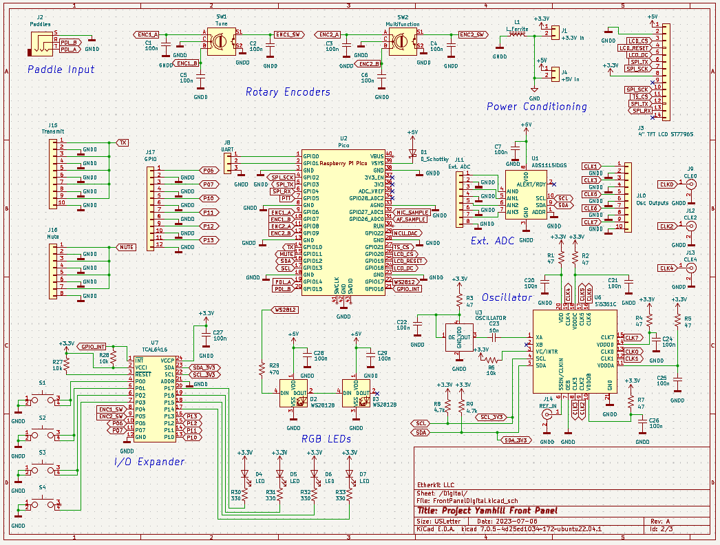
A front panel PCB will hold most of the user interface and brains of Project Yamhill. This PCB will be populated with:
- Raspberry Pi Pico microcontroller
- Color LCD display module with touchscreen
- Large tuning encoder
- Smaller encoders (for multifunction usage)
- AF gain pot if not encoder controlled
- A plethora of microswitch pushbuttons
- A handful of status LEDs
- ADC channels for measuring things like PSU voltage, SWR, etc.
- Two 3.5 mm TRS jacks (Morse paddle and headphones)
- Microphone jack (RJ-45?)
- AF Power Amplifier
- Microphone Amplifier
- Speaker (not sure if front-firing or chassis-mounted)
- Transmit, mute, and extra GPIO pins available on pin headers for project use
- Audio and microphone signals routed to Pico ADC pins for future DSP usage
- Pico DAC pin routed to AF power amp for sidetone use and future DSP usage
The front panel PCB will have a USB connection for programming the microcontroller, as well as at least one UART available for rig control, debugging purposes, etc.
I’ve split the schematics and the circuits themselves into two domains: analog and digital.
Microcontroller and I/O
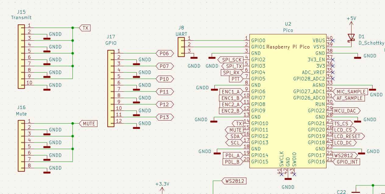
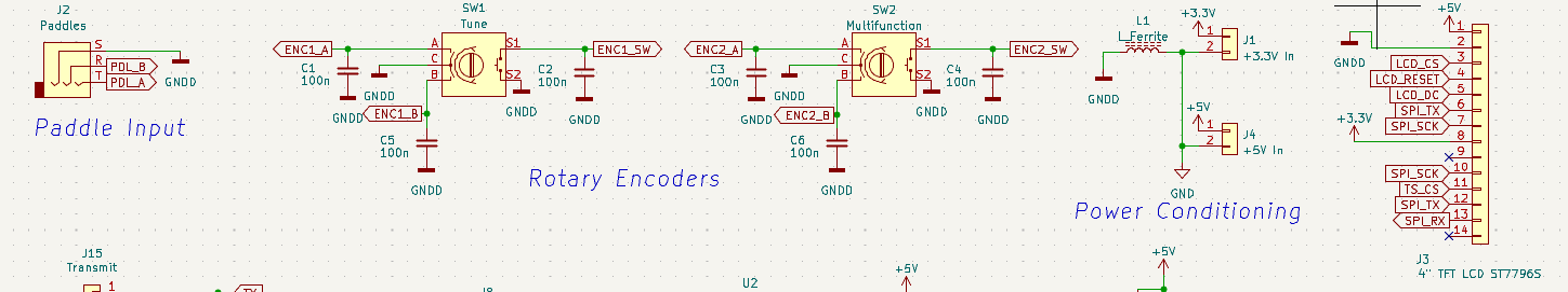
In the first figure above, you can see the chosen microcontroller is the Raspberry Pi Pico. It’s a powerful yet very inexpensive microcontroller on a carrier board with most of the requisite support circuitry already built-in. The carrier board’s built-in USB port will be useful for uploading and upgrading firmware, serial port debugging, and perhaps as a HID device, which will allow the connection of a keyboard.
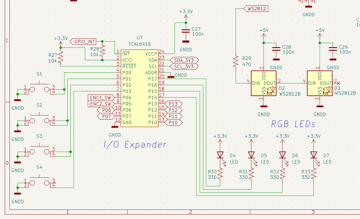
The Pico has a decent amount of GPIO pins exposed, but not enough for our purposes, so instead of looking for a different microcontroller, I decided to add on an I2C I/O expander IC: the TI TCAL6416. This IC is being used for the components that won’t require high-speed I/O, such as switches and LEDs. I’ve also added a couple of WS2812B RGB LEDs as well, directly wired to the Pico, to be used for a T/R indicator or just some pretty ambient lighting.
UART pins are broken out from the Pico to a 0.1” header to use with a GPS module or as a secondary troubleshooting interface. The transmit and mute signal lines are also broken out to headers with hopefully enough pins to cover all possible needs. An external I2C ADC IC with good resolution but low sample rate was added in order to give access to measurements such as power supply voltage level, a SWR bridge, S-meter, or other applications that only need human-readable update rates.
User Interface
The focus of the user interface is a 4.0” touchscreen LCD module, connected to the Pico via a high-speed SPI interface. This should allow for a modern-looking display with the capability for a lot of extension in the future, for features like a menu system or even a waterfall display. Touchscreen capability will allow for a lot of functionality without needing a ton of actual pushbuttons.
Two rotary encoders are included, with one intended as a main tuning dial with a corresponding large knob, and the other used as a multifunction selection knob. A 3.5 mm TRS Morse paddle input jack is a vital addition to this radio experimentation system. Also, four tactile pushbuttons and four mono-color LEDs are added to the I/O expander chip in order to give some important dedicated functions and states their own controls.
Oscillator
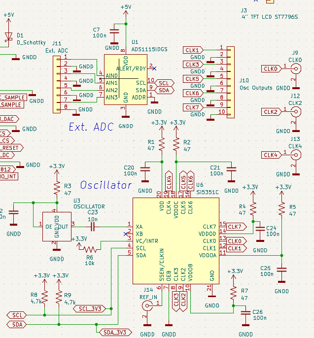
The oscillator system for Project Yamhill is the SI5351C clock generator IC, which can provide multiple stable oscillator signals to the various parts of the system that need them, such as a LO and BFO. It will have a TCXO reference oscillator for stable HF signal generation out-of-the-box, as well as the ability to add an ultra-stable reference clock such as from a GPSDO for the generation of useful VHF signals. Three of the SI5351C clock outputs will be routed to SMA jacks, and the rest of the output pins to 0.1” headers.
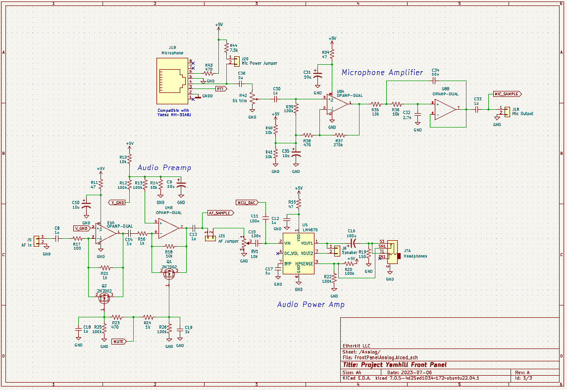
Audio Amplifier System
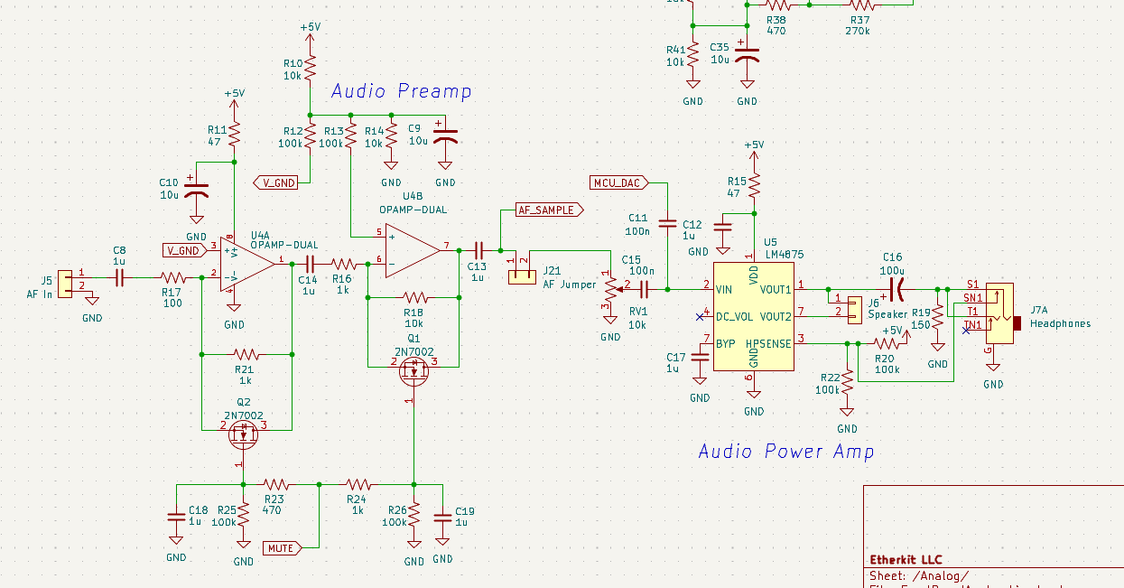
The audio system consists of two gain stages: a 40 dB preamp with keyed muting capability and a 20 dB power amplifier that can drive an on-board speaker or a pair of headphones. AF gain control is provided by a good old-fashioned audio potentiometer, although this could potentially be changed to a digital pot in the future. In preliminary breadboard tests, the muting system works well with a simulated high-speed CW signal.
A jumper is included in order to separate the two audio stages in the future if desired, in order to implement a potential future DSP system, although this is not expected to be used for a while, or be left as an exercise to the ambitious experimenter.
Microphone Amplifier
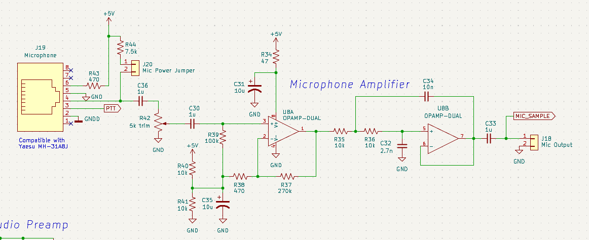
The microphone amplifier is a pretty bog-standard design, consisting of a single-supply op-amp gain stage followed by a Sallen-Key low pass filter. Mic gain is set with simple trim pot, although there may be the chance to change that to a digital pot. The circuit has been designed to accommodate a Yaesu MH-31A8J (the mic used on the Yaesu FT-817 for example), which is a dynamic mic, but the provision for an electret element has also been included. The mic amp output (along with the AF preamp output) are routed to a couple of ADC pins on the Pico for potential future use in a DSP system.
What’s Next
Now that I have a preliminary schematic for the front panel board, the next task is to finish specifying the few parts that I still haven’t done (such as the op-amps and specific controls like encoders, buttons, and LEDs) and then dive into the actual PCB layout. I’ll be working diligently to get this done, as I’m more than ready to complete the first tranche of circuit boards to send out for manufacturing and get some kind of actual prototype project working. Stay tuned and thanks again for your continued support!