Troubleshooting Transceiver Muting Issues
The subtleties of integration
I’m going to try something new for this ‘stack, a paid subscriber only post. In order to provide some added value to those of you have so graciously signed up for the paid subscription option, I plan to occasionally provide you with some additional content that is not strictly needed to see the progress of Project Yamhill (and hopefully future endeavors) but will provide some additional insight into the design process involved in these products. My goal is to produce approximately one a month, as content allows.
In my last post, I talked about some troubles that I encountered when attempting to take a whole bunch of disparate blocks and turn them into a functional (and pleasant to use) transceiver.
The Woes of Integration
The latest happenings on the NT7S workbench haven’t been directly related to the first tranche of Project Yamhill PCBs, but are definitely related to the project as a whole. It’s been a few years since I’ve melted any solder in earnest (meaning in actually building a radio, not just in doing some dumb repairs), so I wanted to…
I’m happy to report that shortly after publishing that article, I cracked the problem and figured out where it was coming from and how to correct it. In this post, I’ll walk you through my process of troubleshooting and how the problem was corrected. As with many such things, the problem did not originate in the areas that I first suspected.
A Quick Look at the Architecture
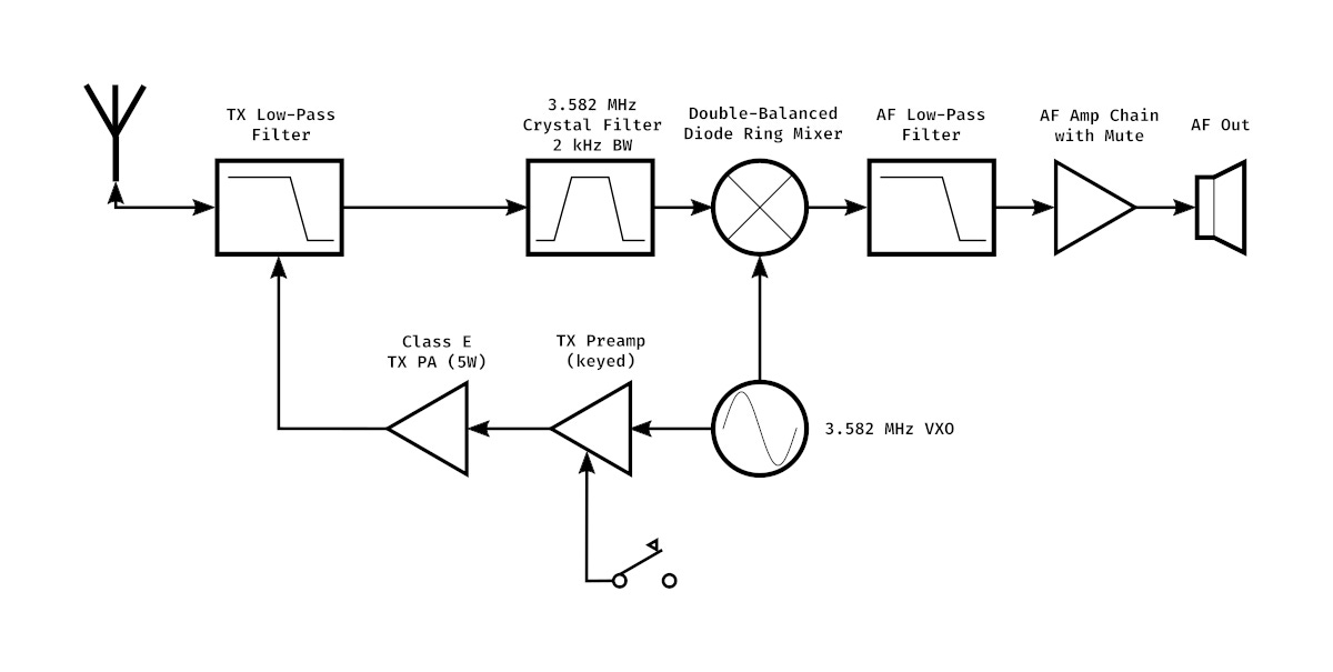
The above illustration is the block diagram of the 80 meter CW transceiver that I’ve been developing as a test platform for some Project Yamhill ideas and as a future ‘cheap & cheerful’ product. The receiver portion of the transceiver is a very standard direct conversion design, made from all discrete components. The main deviations from a typical DC receiver are in the 2 kHz wide crystal ladder front-end filter and the fact that the VXO is only tweakable via a trimmer capacitor, and isn’t really meant to be tuned around. This essentially means that this rig is on a fixed, wide ‘channel’. The 3.582 MHz crystals used in this rig can’t really be pulled very far in frequency range in a VXO, so I made the decision to essentially remove the tuning but use a crystal filter to give good rejection of out-of-channel interference. Even though the receiver is direct conversion, in this particular case, it essentially functions as a superheterodyne would (single signal), but on a single, fixed channel. The intention is to create a ‘watering hole’ type of radio, that is not meant for general use, but hopefully as a way to get in some simple ragchewing and as a way to learn more about simple radio design blocks. Coincidentally, the middle of the crystal filter response is the ARRL 80 meter CW frequency, so some folks could also use this radio to listen to League code transmissions if they are within range to do so.
The Issue
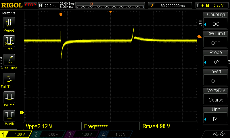
To quickly recap the last post, the biggest problem that I encountered when attempting to take all of the different blocks and put them together into a coherent whole was in the action of the muting circuit. When the transceiver was keyed for transmit, a very loud ‘popping’ impulse was heard on both key down and key up, which made for unpleasant operation. The mute circuit is a simple 2N7000 MOSFET switch inserted in series into the audio path, that is biased to be on during receive and have the gate pulled to ground during transmit. The initial location of the mute switch was just after the AF gain pot, and I ended up moving it to between the final audio amp output capacitor and the headphones port, which helped a bit, but did not actually solve the problem.
Keep reading with a 7-day free trial
Subscribe to Applied Etherics to keep reading this post and get 7 days of free access to the full post archives.


