As Project Yamhill nears actual physical implementation, it’s time to start building some more real-time, two-way communication. We’re starting to get some beta testing and discussions going! If you’d like to participate in Project Yamhill chat, please click on the link below. Thank you!
The last few weeks haven’t been the most productive over my last year, but I have been striving to keep moving forward so that I can maintain momentum, even when things are a little scattered and waiting for all of the parts to fall in place. It didn’t help that the entire family got the crud that been making the rounds, and it’s taken me a couple of weeks to (mostly) recover. I do still have progress to report.
Verifying the Double-Tuned Circuit Parameters
Rather than rely on some pre-generated values for the double-tuned circuit bandpass filters for all of the HF bands (which I’m sure would be fine), when I started designing Project Yamhill, I wanted to turn out my own values based on parameters that I specified. I could have manually used the equations given in a book like Experimental Methods in RF Design, but calculator programs for these design equations exist and work well, so that’s what I decided to rely upon. Specifically, the dtc2008 program from the LADPAC suite that is included with EMRFD.
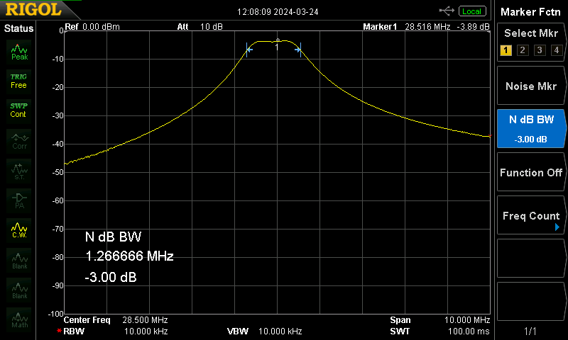
It was easy enough to churn out reasonable component values for each band of choice, but of course you have to actually build and test such designs before turning them loose in the wild. I had previously built a board that had the 20 meter and 40 meter filters and successfully measured that they worked as expected, but there were still the other HF bands to test. This last weekend I needed something relatively easy and brainless to do, so I decided to built up and test more of these designs.
As you can see above, the designs for the 10 meter, 12 meter, 15 meter, and 17 meter filters all look decent. Well, the 12 meter one is slightly lossy and double-humped, which may mean that the coupling capacitor needs to be tweaked, but it’s certainly usable. The only remaining designs that I need to complete are for 80 meters and 30 meters (I’m not sure why I didn’t do the 80 meter design in the document below), which ought to be not too much trouble, given that all of the others have worked well so far.
More Front Panel Woes
As I’ve documented in previous entries in this publication, the Front Panel PCB has been the source of most of my initial headaches with Project Yamhill, which is not surprising since it’s easily the most complicated. Because this board is large and 4-layer, and therefore quite expensive compared to the rest of the boards, I’m working hard to test as much of the current design that I can before ordering another board spin.
The last subsystem to test on the Front Panel is the GPIO peripheral that I’m using (the TCAL6416 I/O expander IC) to control the discrete LEDs and pushbuttons on the board. I wish I didn’t have to resort to an extra IC, but there just aren’t enough exposed I/O pins on the Raspberry Pi Pico board, so it has to be done this way. I somehow lost the bag of TCAL6416 ICs that I had sitting around, waiting for the prototype build, so I never did get to that portion of the testing. I’ve finally rectified that by ordering another strip of ICs and I’ll be installing one and the associated peripherals on my Rev A prototype PCB this week so that I can verify (or not) that it works. Unfortunately, there is no existing Arduino library for this chip, so I’ll have to code the interface from scratch, which may take a bit of time.
Unfortunately another problem with this PCB also popped up. The audio PA uses a LM4875 IC, which gives both headphones and speaker output, with the ability for it to automatically switch between the two based on the headphone jack internal switch contact. The headphone port always worked as expected, but the speaker that I initially chose didn’t really work correctly at all. At best you could hear a tiny whisper out of it. I thought that was probably because I chose one of those tiny PCB mount rare-Earth magnet speakers (it’s something like 10 x 16 mm dimensions). I recently finally got round to replacing this speaker with a more old-school sized 1 W speaker, thinking that would probably fix the issue. Nope, it’s still doing the same thing. So now I also have to troubleshoot this problem before the next board spin as well. I’ve used this IC before, so I know it can do this job. Most likely I’ve made yet another subtle schematic error, which I’ll have to track down and correct. Further updates to come.
Connector Change?
The current interconnect for DC and AF signals on Project Yamhill is the venerable 0.1 in/2.54 mm header (also known as a Dupont connector). I chose it because it’s very widely available and it’s cheap to implement, but there are problems with it that are forcing me to strongly consider an alternative.
Lack of polarity is the biggest problem I’ve encountered so far. I haven’t burned out anything by accidentally switching the contacts yet, but I’m getting the Old Man Eyes now, and it’s straining for me to carefully compare the wire colors with the small silkscreen polarity indicator on the PCB. Not to mention that it’s easy to misalign the plug to the header (off-by-one) and also that the simple friction-fit of the connectors mean that they can easily be pulled out inadvertently.
So I’m considering going with some type of JST connector as a replacement, most likely the JST-XH variant because they are keyed and have the same pin pitch as the current Dupont connectors. I believe they are fairly easy to source, and preassembled wiring harnesses are out there as well. Have any different suggestions? Please leave a comment below!
Looking for QSOs
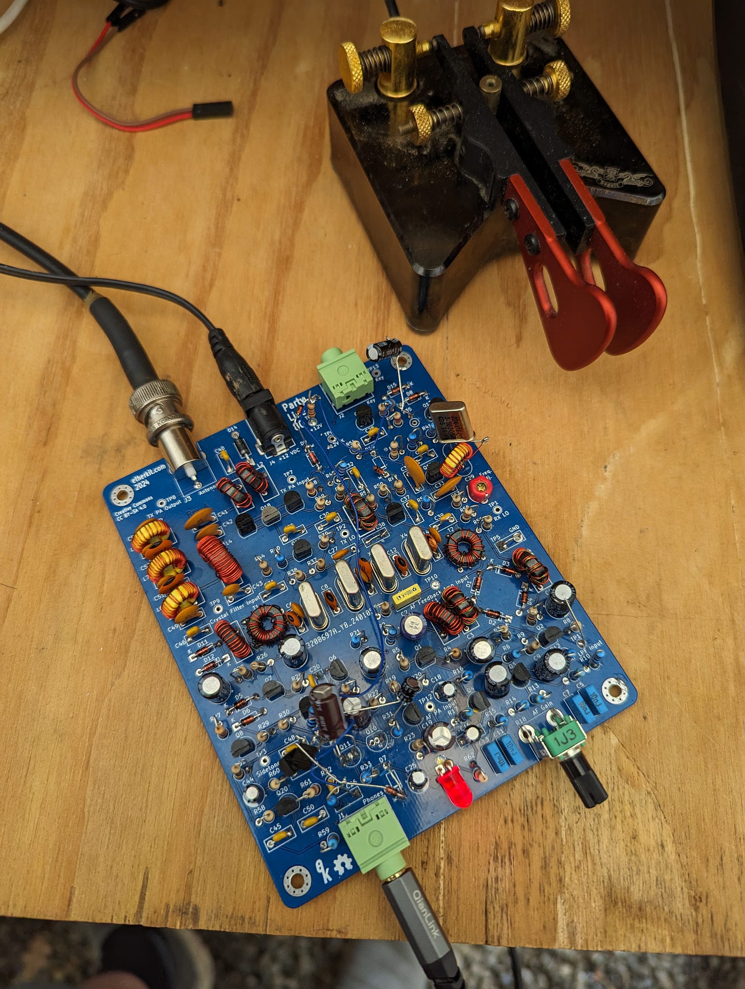
A few posts ago, I mentioned that I recently got my Party Line 80 QRP CW transceiver working very nicely now and I need to get some QSOs on it. The problem is that since you only get significant 80 meter propagation at night, it’s a little tough for me to scare up contacts. Due to my family life and job, I can’t stay up too late on weekdays, although I can do so a bit on weekends. Therefore, if any of you are CW operators, live in the Western US, and have the ability to make a sked during the evening, then please let me know. I may even just try calling CQ some on the next few weekend evenings, so you could set up a HamAlert for NT7S and try responding if you see that I’m QRV. Your help is greatly appreciated! I’m eager to get some real QSOs under my belt with this rig.
What’s Next
I’m very eager to get another set of PCB designs out to the board fab soon so that I can move forward with making Project Yamhill a reality. This is going to entail finishing the things mentioned in the Front Panel section above, doing a Rev B version of the Party Line 80 PCB, and potentially changing all of the DC/AF interconnects to a different connector type.
Once that’s done and I’m waiting for new boards to be fabricated, I’m going to be revisiting the coding side of things, including doing some cleanup work on my popular yet sadly-neglected Si5351 library for the Arduino. All of these “side projects” are meant to ultimately be in service to Project Yamhill as well, as it will need a lot of coding and peripheral work in order to make it a coherent whole, so almost everything I’m doing is relevant to Project Yamhill, even if it’s not immediately obvious right now.


