As Project Yamhill nears actual physical implementation, it’s time to start building some more real-time, two-way communication. We’re starting to get some beta testing and discussions going! If you’d like to participate in Project Yamhill chat, please click on the link below. Thank you!
Wow, it’s been a crazy last few weeks here me, and none of the craziness had to do with Project Yamhill or anything else Etherkit related. A lot of it has to do with my part-time job. While I can’t really get into the details, I’ve been dealing with some unpleasant things in that department. Not to mention that I’ve had a couple of other personal curveballs thrown my way lately. Nothing devastating, but issues that demanded my attention over other work which I’d rather be doing. Things should be back into a more normal routine soon enough.
Party Line 80 BPF Redesign
A few weeks ago, when I was doing some on-the-air testing with the Party Line 80 CW transceiver, I noticed there was a mass of digimode activity in the passband of the receiver, which made trying to listen for the W1AW bulletin virtually impossible. It sounded like FT8 to me, which seemed weird because the 80 meter FT8 frequency is supposed to be 3.573 MHz, which should be well outside of the passband of the front-end filter (about 2 kHz wide, from approximately 3.581 kHz to 3.583 kHz). I had totally forgotten about JS8Call, which was actually the signals that I was hearing. That mode seems to operate north of 3.578 kHz.
I originally designed the front-end crystal ladder filter to be approximately 2 kHz wide with the idea that it would be nice to give the user the ability to tweak their operating frequency within that passband a bit to give some variety, not realizing just how many digital modes are very closely adjacent to 3.5815 kHz. Upon further thought, it seems like it would be better to more closely “channelize” this rig so that all of them are essentially on the same frequency. There won’t be a ton of elbow room from the digimodes.
With that in mind, I made the executive decision to narrow the receiver passband a good amount. Going back to my lab notebook to retrieve the crystal parameters, it was easy enough to plug them back into the Dishal crystal ladder filter design program to see what filter bandwidth would give me a reasonable termination impedance for matching to 50 ohms and capacitor values that made sense. It didn’t take long to settle on a bandwidth of about 880 Hz, which gave an impedance of around 800 ohms, easy to match to 50 ohms with a wideband 1:4 ferrite transformer. This is still wide enough that it shouldn’t be fatiguing to listen to, but narrow enough to eliminate most of the adjacent digimode signals.
Here is a plot of the original filter with the ~2 kHz passband. Note that the skirts on this filter are not that steep, which is why I’m sure I heard all of that JS8Call activity a few kHz below my target receive frequency.
After getting the new parameters from Dishal, I built up a prototype of the filter on some copper clad with SMA terminations so that I could easily validate the design on my spectrum analyzer. I was please to see that the actual circuit closely matched what was predicted by the design program, even though I used capacitors that weren’t super close to the values that it called for. That gave me the confidence to change out the capacitors and rewind the transformers in my Party Line 80 prototype. The new filter sounded good and worked like a charm!
If you compare the Delta markers in each of the above plots, you’ll see that the original filter was only down about 40 dB from the passband at 3 kHz lower in frequency. The new and improved filter however, shows over 60 dB of difference. This following measurement shows that the filter is very close to the target bandwidth, which is fine given the capacitor values that I picked weren’t incredibly close to the calculated values.
Party Line 80 Case Design
A few months ago, I delved into a ton of FreeCAD tutorials on YouTube so that I could learn a bit more than the most basic skills in that program, enough to be capable to design my own enclosures for future Etherkit products that could be printed on a FDM 3D printer by me or anyone else who wanted one. I must say, FreeCAD is fairly powerful but also incredibly arcane, and it has a steep learning curve. I’ve been drafting and using CAD for a long time and I still struggle to understand how to do things in FreeCAD, but it’s FOSS, so I can’t complain too much.
Anyhow, I managed to cobble together a parametric design that would allow me to punch in the dimensions of the PCB that would be housed by the enclosure, and it would generate an enclosure of the appropriate size, which I can then export out into a new file and then customize with the holes for the controls and connectors, and add the necessary labeling. The design comes in two halves, a bottom and front panel half, and then a top and rear panel half. Threaded brass heat-set inserts are used for securing the PCB to the bottom case half and for securing the top of the case to the bottom.
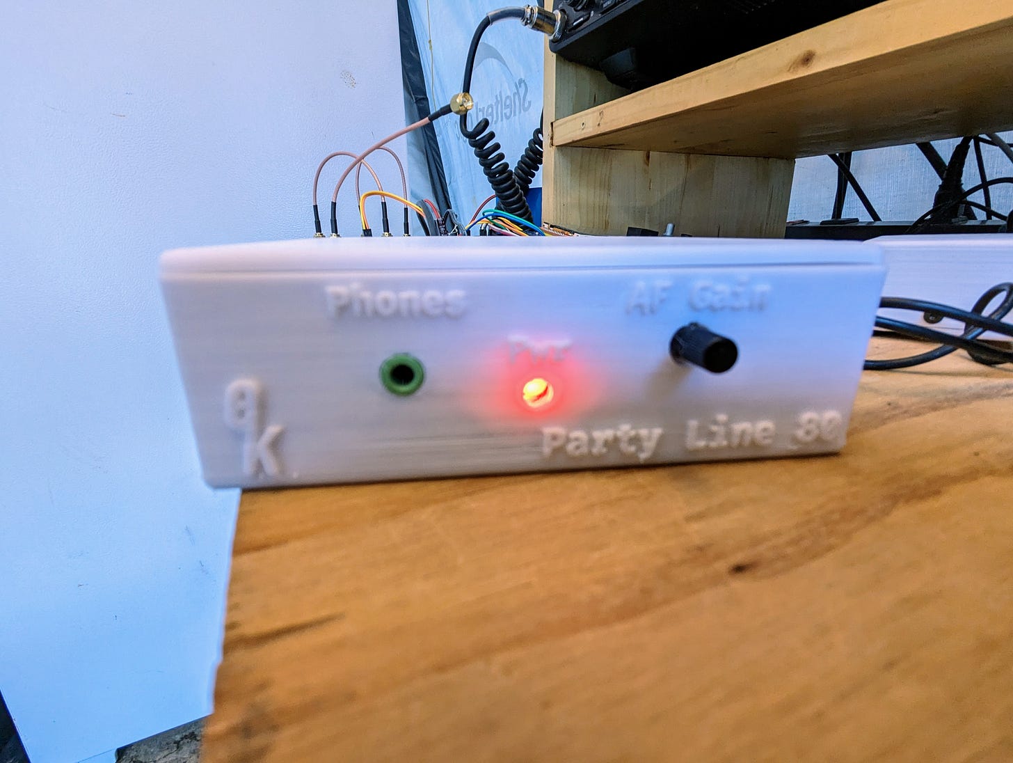
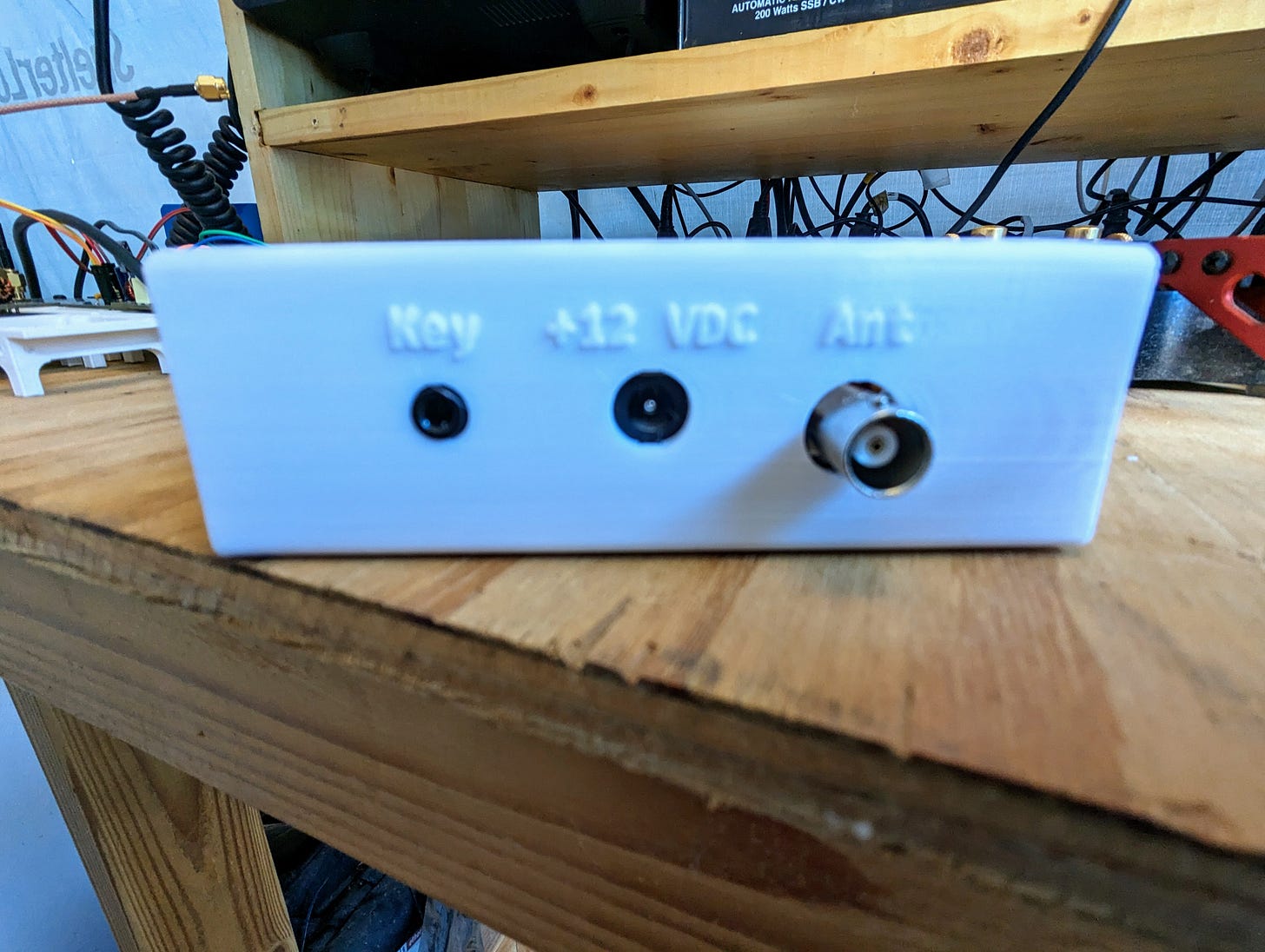
The first iteration of this design was used for EtherKeyer Mini and appeared to do a pretty good job for this purpose. I did have to fix a few bugs when I had it try to spit out a design for Party Line 80, but that wasn’t too much trouble, just some minor things. It took me a ridiculous amount of time to figure out how to properly import the Etherkit logo so that I could pad it out on the front panel, but once I powered through that the rest of it came together nicely. Here are a couple of photos of the design printed out in PLA. It doesn’t look that nice because I used faster, draft settings, but it’s still pretty awesome to see the product all buttoned up in a proper case.
I’m really looking forward to getting this product shipped out soon so that I can check it off my list. I’ve been holding onto this giant case of ~3.5815 MHz crystals for a very long time, wanting to do something fun with them. I think this will be an enjoyable project for kit builders to assemble and put on the air.
What’s Next
Finishing the Project Yamhill Front Panel Rev B spin is definitely next up in the work queue. I’ve got all of the schematic changes implemented and I’m currently working on the redesign of the PCB layout. Once that is done, Party Line 80 Rev B respin will be knocked out so that I can batch up multiple respin boards together in the same order from my PCB vendor. I may respin EtherKeyer Mini as well, but I need to do a little more thinking about that and some testing. I’m ready to get some of these new products back to market, and perhaps an old popular product as well…


