As Project Yamhill nears actual physical implementation, it’s time to start building some more real-time, two-way communication. If you’d like to participate in Project Yamhill chat, please click on the link below. Thank you!
Let's Chat
Now that I’m getting close to having some real boards ready for testing, it felt like it was time to launch the Etherkit/Applied Etherics chat server. I don’t use social media any more, but chat services are a great way to interact in real-time, something which can’t be done on Substack. This will become critical once people other than myself start atte…
I hope you had an enjoyable and restful Christmas, if you celebrate. I took a few days off myself, so I don’t have any major progress report for you today, but rather a compendium of smaller updates that I haven’t been able to fit into other posts yet.
Project Yamhill BNC Antenna Board
Let’s start off with the least exciting board in this entire collection. The RF interconnects in Project Yamhill are all SMA but most QRP (and QRP-ish) radios these days use BNC antenna connectors, so I designed a simple board designed to allow one to connect a BNC to an SMA, while being mechanically secured to the chassis.
I don’t know if there will ever be a 100 watt RF amplifier for Project Yamhill, but I figured that there probably will be at least a 20 watt board. I was curious just how much RF a SMA connector could take and it seems in doing some research that it can easily handle at least 600 watts at HF levels, which kind of surprised me. So the only place where a BNC will be used is at the antenna connection.
Project Yamhill 1x1 ProtoBoard
This board is still very much a work-in-progress. The ability to prototype circuits on a pre-made PCB specifically designed to integrate with Project Yamhill seems pretty important. In the design below, you can see that I’ve created a variety of isolated square pads, along with exposed soldermask tracks allowing access to the ground plane. There are spots for input and output connectors, both pin headers and SMA. These connectors are routed to a larger rectangular pad. A power supply header is at the top of the board and the positive pin is routed to a long pad which runs down the middle of the board.
I eventually want to create multiple variations of this board, including one with a DIP/SOIC socket, and one with a larger 1x2 form factor. However, because I’m fairly sure I’ll be doing some revisions to this design, I’m going to start with this one first and “eat my own dog food” for a bit before trying to crank out some alternate designs.
Twin-T Code Practice Oscillator
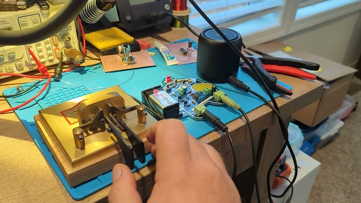
I was recently going through my boxes of all of my Etherkit stuff packed from our move, looking for various components needed for Project Yamhill prototyping. One thing I stumbled upon was a Twin-T code practice oscillator PCB design that I created back in 2021. It’s a very simple circuit, with the aforementioned Twin-T osc feeding a simple two-stage op-amp low-pass filter/buffer, fed to a headphone output. The PCB design is an original creation by my youngest son Eli, and it depicts a crewmate from the popular game Among Us. I built one of these boards up and it sounded pretty nice! (I don’t even think I got to that stage previously, as these were created just before we pulled the ripcord on Beaverton and made the long journey out to rural Yamhill County). Here’s a short video of it in use. I’ve connected the output to a small amplified speaker and I’m keying it with an external keyer.
So my question to you is, do any of you think you could put this to use to entice or help kids learn Morse Code? I’ve got a handful of PCBs left over, and I’d be willing to give some away in order to help kids. If you’re interested, hit me up in the comments or better yet join my chat server, and perhaps I’ll send you one for free.
Perhaps I’ll even end up selling these kits after a little more refinement, if there’s interest in it.
Vibroplex Brass Racer Finger Pieces STL Model
As mentioned above, at one point not that long ago, all of my ham radio and electronics stuff was packed away in boxes, which were sitting in a storage unit. I used copious bubble wrap to protect all of the heavier items, and pretty much everything survived intact except for one item: the finger pieces to my Vibroplex Brass Racer snapped. I know that theoretically you can purchase replacement parts for these, but I wanted to exercise my 3D CAD muscles, so I decided to try to create and print my own version. With some digital calipers and FreeCAD, I was able to make pretty short work of this project.
I placed the STL file for these finger pieces up on Printables in case anyone else happens to need some. I figure some search engine indexing of this should be helpful to a few people over the years.
Party Line 80!
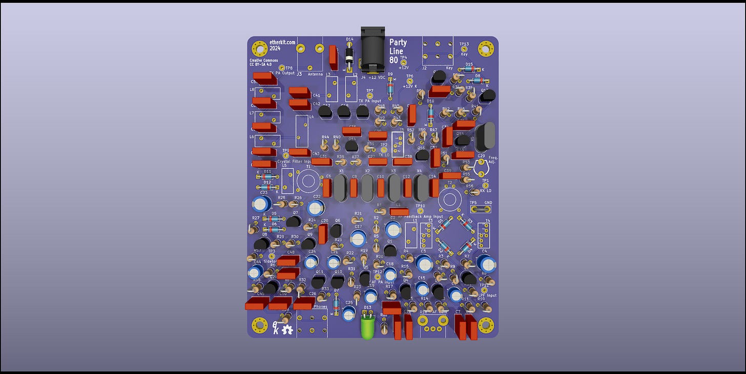
The mysterious direct conversion CW transceiver that I’ve been occasionally talking about now has a name: Party Line 80. I figured that made sense, due to being rockbound on one spot on the band. Here’s the PCB design, ready to go to fab:
I imagine that I will be selling this as a kit at some point (at a cheap price point), but at first my plan is to give some away in connection with the activity of this ‘stack. Perhaps as referral rewards? I’d also like to do some kind of modest QSO activity event, but I’m not 100% sure what form that would take yet. I’m certainly open to suggestions.
Etherkit Relaunch?
At this point, I’m strongly leaning towards relaunching Etherkit in 2024. I’ve got some designs that I think will be kit-able, and I would like to find a way to sell Project Yamhill modules as well. At the very least, I want to be able to sell the boards, but I’ll be disappointed if that’s all I end up doing on the hardware side. I don’t have many details yet, as I’m still working them out, but I do want to find a path forward on Etherkit, even with the current space constraints that I have here at our new house.
300 Subscribers!
The heading says it all. Getting 300 subscribers in less than a year for a Substack with such a niche topic is a very pleasant surprise. Thank you to all who have subscribed and double-thanks to my paid subscribers! So far, a lot of the content here has been long on design and theory and short on implementation. That’s about to change, as you’ll see next…
What’s Next
At this point, I’ve done enough design, prototyping, and PCB layout that I’m confident that it’s time to order all of the current tranche of Project Yamhill PCBs (and the Party Line 80) from the fab. I’m going to go back and do one final review of each PCB design, since I know there are already a few tweaks that I want to do on various boards. The biggest one is that I’m going to try to convert the front panel PCB from two layers to four layers. It was insane of me to even try to make it a two layer board, but four layer boards aren’t nearly as expensive as they used to be, so it makes a lot of sense to make such a dense board a four layer design.
My goal is to get all of these changes done by next week and get the designs in production by then so that I can beat Chinese New Year. Once I get all of these boards back, I’ll have a huge pile of building and validation to do, so that’s what’s next on the horizon. I just received a large Mouser order of prototype parts, ready to stuff on PCBs, so once those boards arrive, it will be game on. And speaking of prototype parts…


I stumbled upon Etherkit a few years ago only to find I had missed the boat on the CC1. But the Party Line 80 looks like a reasonably straightforward build and I want one! Have you given much (any?) thought to rebooting Empyrean? I have one and it sits there staring at me begging to be put to use, I will need to use it to learn how to write Arduino code first, though! It sure seemed like a cool project.