


As Project Yamhill nears actual physical implementation, it’s time to start building some more real-time, two-way communication. We’re starting to get some beta testing and discussions going! If you’d like to participate in Project Yamhill chat, please click on the link below. Thank you!
Let's Chat

Now that I’m getting close to having some real boards ready for testing, it felt like it was time to launch the Etherkit/Applied Etherics chat server. I don’t use social media any more, but chat services are a great way to interact in real-time, something which can’t be done on Substack. This will become critical once people other than myself start atte…
This week I was able to get the audio circuitry of the Front Panel PCB assembled and working well enough that I could take it, along with the modules from the first tranche of boards and an external Si5351A VFO, and make a working receiver! There are still some bugs to work out, as I will detail below, but the basic idea works!
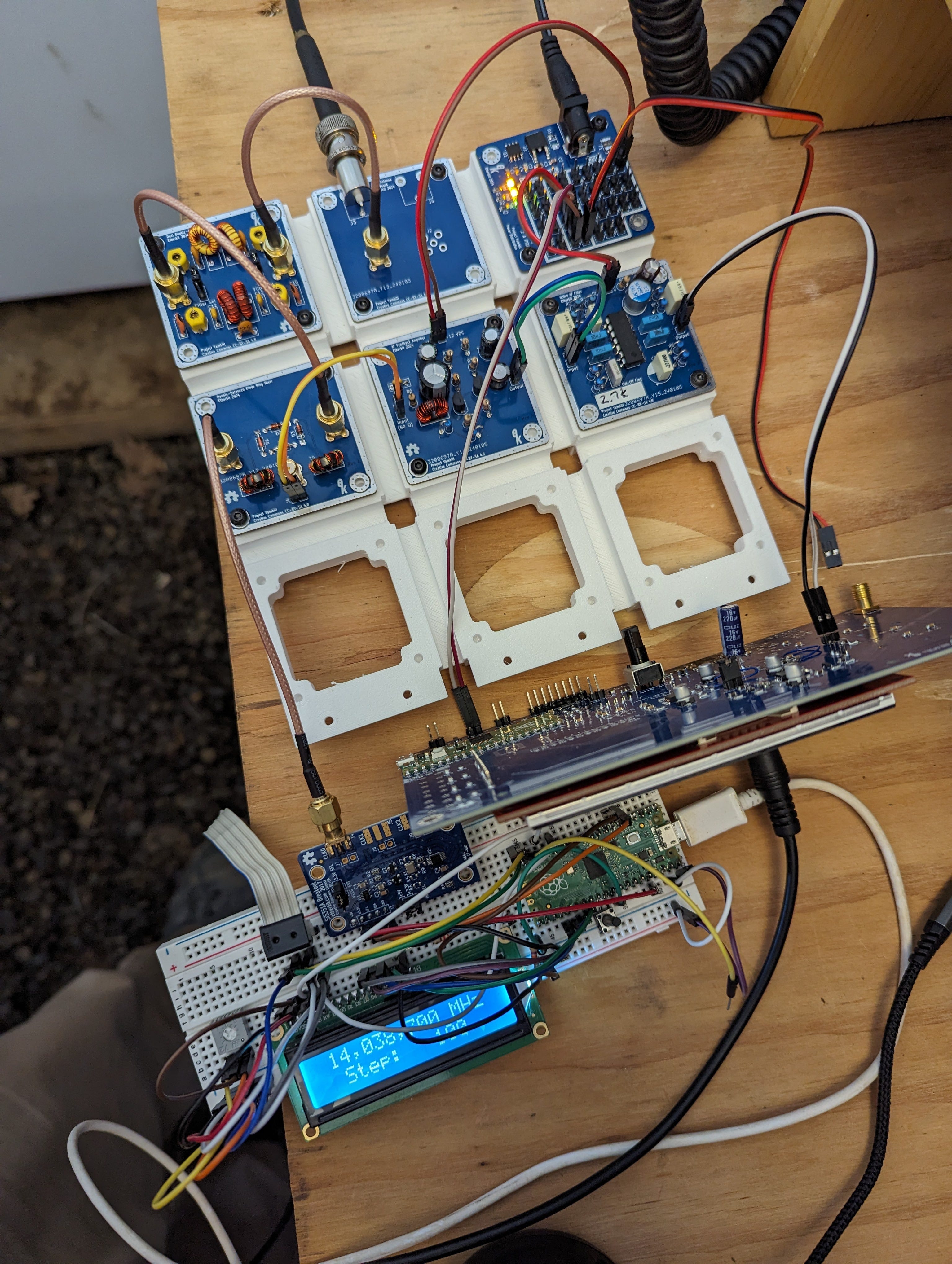
Above you can see, I used one of my prototype chassis sections with the antenna board, PSU, dual double-tuned circuit board, double-balanced diode ring mixer, W7ZOI audio feedback amp, and op-amp active audio filter. Power and audio interconnects are done with Dupont pin jumpers and RF interconnects with RG-316 coax terminated in SMA plugs.
Here’s a band scan video of the direct conversion receiver tuning through the 20 meter band here in the early afternoon (bonus doggo content too). The bands aren’t actually all that lively in this video, but there’s enough going on to give you a sense of the receiver working. There’s quite a bit of higher-frequency hiss in the audio, because I didn’t use the active audio low-pass filter when recording this video. Why, you might ask? Because the active filter introduced more high-frequency hiss than the receiver had without it! Oops. Also, you can here a low-level buzz pulsing about every 2 seconds. I suspect that’s from the Raspberry Pi Pico, but I haven’t really even begun to track that down or mitigate it yet.
I checked 40 meters with this receiver just after the sun went down and there was a lot more going on. I’ll capture of video of that for the next post.
Changes to Be Made
Even though I’m thrilled that the basic concept works, there’s a lot of work to be done on the front panel PCB. I don’t feel quite as bad about making that screw-up with the Si5351C footprint, since there are quite a few other things I’ve found that need to be fixed. These include:
Feedback capacitors missing from the audio preamp.
I wired the mic connector pins backwards (although I was able to confirm that the actual mic amp works correctly because of the signal on the shield, lol).
The wrong footprint for the audio PA.
The tiny little speaker that I chose for the front panel is not suitable. The output is very anemic. It should in theory be able to handle 1 W output, but you can only barely hear it. I’ll double-check with a different speaker in order to make sure, but I’m pretty sure I’ll need something different here.
Add an audio detector for future AGC purposes.
Some ergonomic tweaks.
As painful as it was to screw up that front panel board, I’m just going to chalk it up to a $100 lesson.
What’s Next
I’m going to work on troubleshooting the active audio filter so that I can get that in-line in the receiver, which will produce much more pleasant audio. In parallel with that will be a big push to correct all of the front panel PCB and circuit issues so that I can order another batch of those boards and get a full prototype up and running.
I’d also like to get back to Party Line 80 to fix the muting issue that cropped up on the PCB version that’s not on my Manhattan-construction prototype. I’ve been using EtherKeyer Mini to make all of my CW QSOs on my IC-7300 (I try to make at least one CW POTA QSO every day I’m at home), and so far it’s been working well. I’m looking forward to getting those two working together and making some QSOs with that rig.