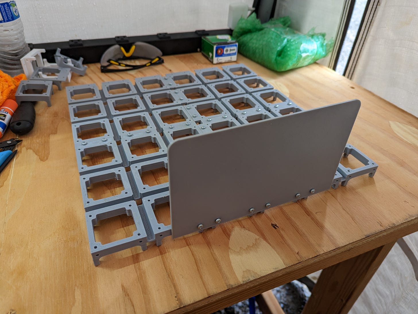
Project Yamhill Prototype Backplane
This post is a bit later than I hoped it would be. I had a hiccup in printing the last section of the backplane that resulted in a print that was 80%, and a lot of filament was wasted. I had to wait for more filament to be delivered, and that delivery was delayed a couple of days. I did finally manage to complete and assemble the first backplane print, and I think the result is decent.
The print tolerance is good enough that the sections assemble well and mechanical stability of the assembly is good. As you can see in the photo above, I printed a blank front panel just to get an idea of how a real front panel would fit with the backplane, and to see how the chosen thickness would hold up mechanically. I do wonder if perhaps the size will be a bit cumbersome for some folks, but I don’t want to cut short the amount of room available for more complicated projects.
It’s clear that I’m going to have to assemble a mini print farm in order to produce these backplanes in bulk, since the printing takes quite a bit of time on my old school Ender 3. I’ll definitely have to look into faster printers.
PCB Templates and First PCBs
The power distribution PCB hasn’t been laid out yet, but I have created template projects in KiCad for 1x1 block and 1x2 block PCBs that I can use as the basis of future boards. As I’ve mentioned in my previous post, the next item on my task list is to layout the power distribution/PSU board. I also plan to create a 1x1 block and 1x2 block prototype board with “Manhattan”1 pads that can be used to free-form build circuit blocks for Project Yamhill. This will allow me and other interested parties to immediately get to building a radio before I have all of the specific block PCBs created. Pretty soon I should be looking for interested beta testers who have experience in building their own radios, so stay tuned for that.


Hmm... The footprint does look pretty large. Could the two outside edges be hinged so they rotate up 90 degrees and fit behind the outline of the faceplate?