As Project Yamhill nears actual physical implementation, it’s time to start building some more real-time, two-way communication. If you’d like to participate in Project Yamhill chat, please click on the link below. Thank you!
Let's Chat
Now that I’m getting close to having some real boards ready for testing, it felt like it was time to launch the Etherkit/Applied Etherics chat server. I don’t use social media any more, but chat services are a great way to interact in real-time, something which can’t be done on Substack. This will become critical once people other than myself start atte…
First The Agony
The Front Panel PCB was by far the most complex board in this entire project, and it was also my very first 4-layer PCB design (and relatively expensive to boot), so I was more than a little nervous that I would screw it up. Turns out that I did have at least one-deal breaking error, but not in the area in which I expected.
After building a Power Distribution module and verifying its basic functionality, I started on the Front Panel by assembling the audio amplifier sections and noticed my first error. I accidentally used a TSSOP footprint for the LM4875 audio power amp, when I only had SOIC versions on hand. However this wasn’t a show-stopper, as you can get that IC in TSSOP packaging, I would just need to order some of those. OK, so that would delay me in bringing up the AF amp section, but I could move onto the digital parts.
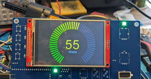
The Raspberry Pi Pico was easy to install, and the 4 inch LCD module went on exactly as expected. It didn’t take long to load up a LCD test sketch and verify that the module connections were correct. After that it was a quick operation to install the two WS2812B RGB LEDs and confirm that they were also working as expected.
Next I wanted to install the SI5351C clock generator IC so that I could generate a VFO signal for the first Project Yamhill radio project, the direct conversion receiver. After installing all of the related passive components, things went south when I went to install the Si5351C IC. It literally only comes in a QFN package, which is challenging to hand-solder. I have a good hot air rework station, and I used plenty of flux and was sparing with the solder paste but the stupid thing did not want to mount correctly. It keep sitting at an odd angle when I would apply heat for reflow. Without getting into the weeds of my troubleshooting woes, I did finally figure out the issue after hours of struggle. I used the wrong footprint for this IC.
Apparently there are a large number of similar, but different footprints for what is nominally a QFN-20 component. Lots of closely-sized but different lead pitches. Many different exposed pad sizes. My problem is that the footprint that I used had an exposed pad outline that was smaller than the one on the actual device. This wouldn’t be the end of the world except for the second problem: the other pads on the perimeter of the footprint very slightly intruded into the are of the exposed pad in the center of the IC. So some pads were always being shorted out. It was a very subtle size difference, which is why it took me a while to figure it out.
I tried my best to attempt to work around the problem by grinding away some of the insides of these pads, but I just didn’t have the dexterity to do this without breaking traces and grinding away too much pad. So I’m going to have to give up on Rev A being a fully-functional board and move onto a Rev B design. Unpleasant.
Now The Victory
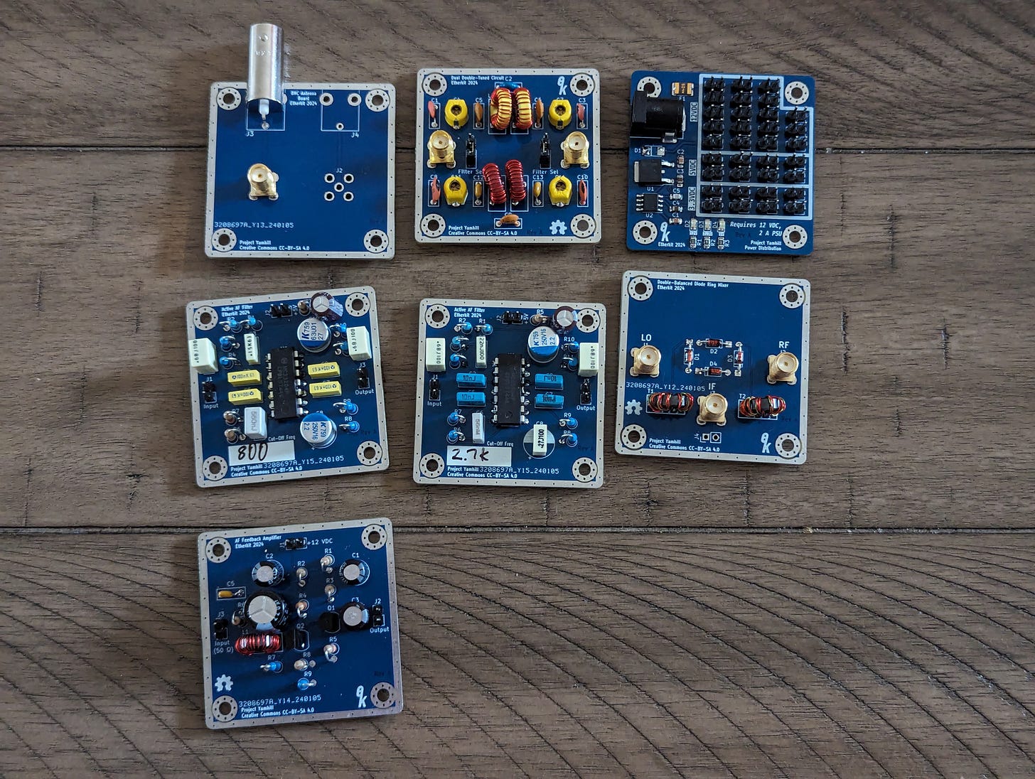
The good news is that I was able to assemble and do initial testing of all of the other Project Yamhill modules and they all seem to work as expected. Here’s the handsome family of the first tranche of boards:
As you can see above, I built two different versions of the Active Audio Filter board, one with a cutoff frequency of 800 Hz and the other at 2.7 kHz. I don’t have an audio signal analyzer (definitely on my wish list) but with a signal generator, oscilloscope, and spreadsheet I was able to determine that the frequency response was pretty much what I expected.
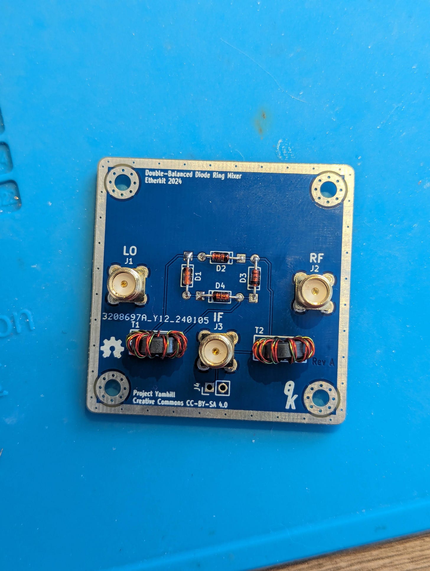
The diode ring mixer was an easy and quick build, and it was simple to put it on the spectrum analyzer, driven by my 2-channel arbitrary waveform generator to confirm that it had the mixing, conversion loss, and LO suppression figures that one would expect from such a device.
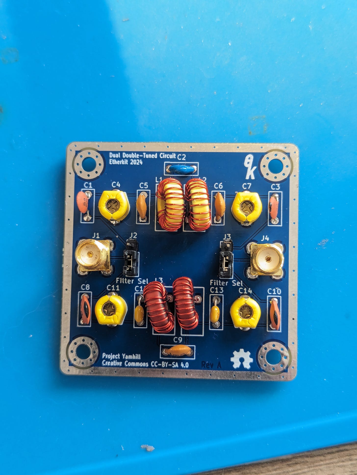
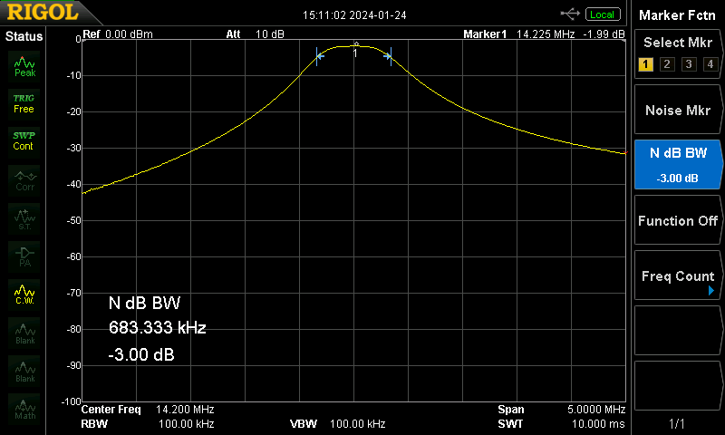
For the Dual Double-Tuned Circuit board, instead of relying upon published filter values, I started with my own parameters and used the LADPAC software provided with Experimental Methods in RF Design in order to create receiver bandpass filters for all of the HF bands.
So far I’ve built the 20 meter and 40 meter filter designs and they peak up exactly within the designed band and have a loss of around 2 to 3 dB. Nice!
EtherKeyer Mini
In more encouraging news, I got my low-power ATtiny85V microcontrollers in, and was able to tweak the clock settings a bit in my fuses and sketch so that it should be able to operate down to 1.8 V, which will allow it to run off of a CR2032 cell through its entire discharge curve.
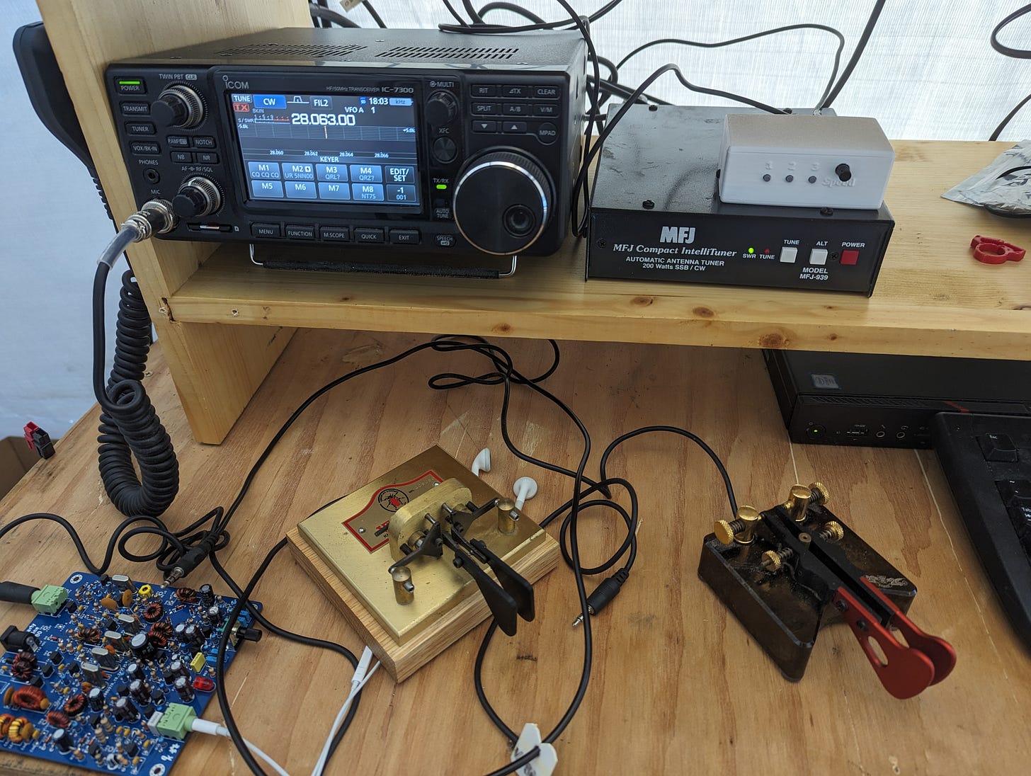
In the interest of “eating my own dog food”, I’ve installed EtherKeyer Mini on my IC-7300 and plugged my Begali Simplex into it. As I’ve mentioned before, I’ve set an informal goal of making at least one CW POTA QSO every day that I’m at home with my station. I’ve changed the IC-7300 to straight key mode and I’m only going to rely on EtherKeyer Mini for my keying functions. Keyer Memory 1 has my callsign programmed into it for POTA chasing. I’ve already made two POTA QSOs today with the setup, using the message memory (and even having to cancel a message in the middle of playback when the activator sent his callsign twice instead of once and I jumped the gun sending mine). So far it works FB, and I’m looking forward to shaking out any bugs.
If you’re a CW op who has some comfort with using command line tools and wouldn’t mind having to occasionally flash new firmware, and would like to beta test EtherKeyer Mini, hit me up, as I should be ready to send some out for testing in the near future.
(On a side note, POTA has been such a great way to ‘gameify’ ham radio for me. Some of us don’t really like to ragchew, but do like to use radio to try to hit certain goals and test our abilities. Long live POTA, SOTA, and the other operating activities that give our hobby spice!)
A Plea
I will have a full post on this in a few weeks but I wanted to put this out here in a small way in this post:
It’s been almost a year since I launched this Substack with a pretty lofty goal for one guy to execute. It got a slow start because I was still in the middle of securing the construction of our new house early last year, but once that was done I was able to step up and follow through with much of what I set out to do.
All of the prototype boards (especially the failed Rev A Front Panel) and components are quite expensive to fund, and I’m a bit concerned that it’s going to be difficult to keep funding this endeavor until I can make it self-sustaining by having sellable products. If you like what I’m doing, have gotten something out of this journey, and want me to be able to continue, please consider becoming a paid subscriber. I believe that I have demonstrated that this isn’t just a pipe dream, and that I’m committed to putting the time and resources to make this a reality. Thank you.
What’s Next
I’m going to build up the rest of the Rev A Front Panel PCB that I have so that I can confirm that the rest of the circuits are working as expected. Since I have to pay for the manufacturing of a new set of boards, I want to do everything that I can to make sure that there are no more major flaws.
Once the audio part of the Rev A Front Panel is built, I plan to take all of these modules, along with an external VFO, and build the first Project Yamhill radio project: the direct conversion receiver. Should be really exciting to get to this milestone! Stay tuned!

