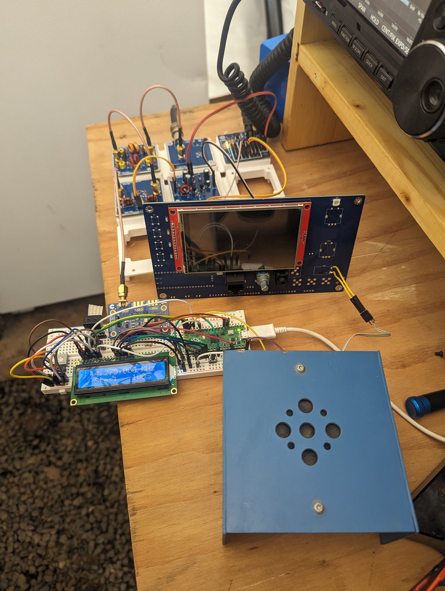
Towards Front Panel Perfection
Or something resembling that
As Project Yamhill nears actual physical implementation, it’s time to start building some more real-time, two-way communication. We’re starting to get some beta testing and discussions going! If you’d like to participate in Project Yamhill chat, please click on the link below. Thank you!
The work to shake out as many bugs as possible in the Project Yamhill Front Panel continues in earnest here in Oregon Wine Country. Given that this is not exactly exciting and glamorous work, this won’t be a large update, since most of my work over the last week has consisted of troubleshooting subtle problems and substituting components one at a time, then testing. That’s a tedious process of refinement that doesn’t lend itself to great reading, unfortunately.
So let’s review the problems that I’ve been trying to alleviate this week. First off, I was quite unhappy with the anemic level of audio coming from the small speakers that I chose as prototypes. I tried pushing the gain on the op-amp audio preamp that precedes the LM4875 audio power amp, but that then induced some horrible self-oscillations at around 150 Hz when the AF gain was advanced more than about halfway.
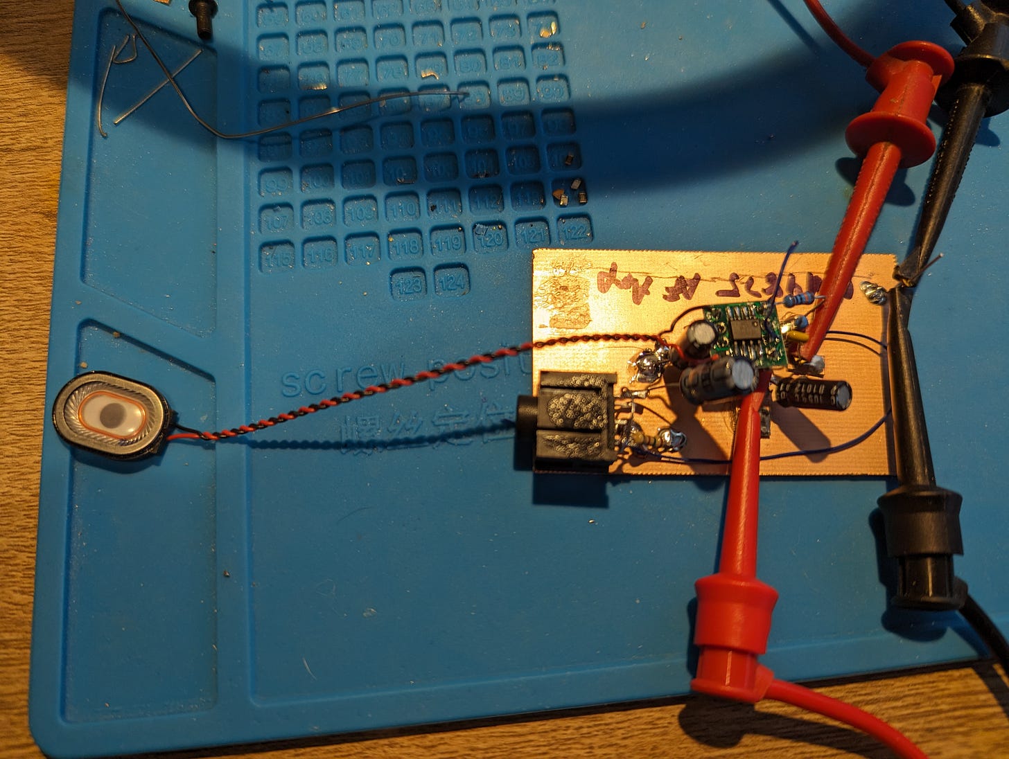
Because my prototype Front Panel PCB was getting a bit haggard from all of the rework that I’ve been doing on it, I decided to breadboard the LM4875 audio PA on its own piece of copper clad, which would make it easier to change components and wouldn’t matter much if I messed it up. Also, isolating circuits as a troubleshooting strategy has always worked well for me. Subtle interactions with other subsystems are sometimes hard to spot in an integrated system.
I believe that this turned out to be a good choice, as I was able to reproduce the same problems on this newly-built circuit when I connected it to the existing audio preamp. As is typical with these modern ICs, they don’t take a lot of supporting components and the reference design is usually quite simple. In this case, I deviated from the reference design in one way that bit me. I added a decoupling resistor on the power rail, which was the only real difference between my circuit and the reference. Turns out I shouldn’t have done that. Removing that resistor solved the self-oscillation problem.
Still, the audio was pretty anemic and worst yet, CW sounded really terrible tuned to around 500 to 700 Hz audio frequency. I was always skeptical of the small speakers that I decided to try to integrate into this PCB (you can see one in the photo above), but the specs claimed they could handle around 1 watt with what seemed to be a decent SPL. Going back to the speaker datasheet revealed another one of the problems. The self-resonant frequency of the speaker above is right at 600 Hz. That might work well if you want a piezo buzzer type of sound, but is really rough to listen to if you want audio fidelity. In order to verify this was actually the problem, I borrowed an old-fashioned paper cone speaker from another project and hooked it up to the audio PA output, and it sounded significantly better (and more sound output power was generated as well).
The problem of weak audio was still present, however, so I needed to figure that out in order to put this audio chain to bed. Since the audio PA is configured to give a fixed gain, I needed to look at the audio preamp for the solution. This preamp consists of a TLV9362 dual op-amp (specs are similar to the NE5532). There are two cascaded stages, giving 20 dB of voltage gain per stage. I had neglected to add feedback capacitors on the initial PCB design, which resulted in horrible hiss out of the first version of this circuit, of course. However, it wasn’t hard to piggyback some MLCC SMD capacitors over each of the feedback resistors in order to get that function working on this circuit board. Temporarily removing these caps showed that I can get plenty of audio out of the audio PA when the preamp is unfiltered, but of course that’s not suitable for actual listening. So I’m going to add at least one more op-amp stage (probably two, unless I find I need the second op-amp stage for something else, like a buffer) to the preamp, all with feedback capacitors, so that the LM4875 can be driven to its full potential.
What’s Next
At this point, I believe I’ve shook out all of the problems from the Front Panel PCB that I can, so I’m going to start working on the Rev B schematic and layout in KiCad. In addition to the additional audio preamp stage, I’m going to put in some kind of audio AGC detector for future use (which may take up one of those op-amp stages for use as a buffer). I will probably also either add some kind of bypass for some of the audio preamp gain stages, or made the gain adjustable in some way, as the amount of audio gain needed for a direct conversion receiver is not appropriate for a superheterodyne. So many little considerations like that!
Regarding other parts of Project Yamhill, I already redesigned the Active AF Filter PCB to use two dual op-amps instead of a single quad op-amp package. I’ve also created a custom footprint that has a PDIP-8 and SOIC-8 footprint in the same area, so that either type of package could be used. This will allow better quality op-amps with better availability to be used. I’m also going to be working on Party Line 80 Rev B, so that I can get all of the above mentioned boards ordered from the fab at the same time.
I’m still looking to make some skeds for initial Party Line 80 CW QSOs, so if you’re a CW op who has a station that can operate on 80 meters, I’d love to make a QSO with you. Message me here or better yet, join the Etherkit chat room and hit me up.


Those very small speakers only work 'reasonably' when they are in a well formed case mostly like a caving in a pc monitor or the housing of laptop. That takes care of the bad frequency respons in open air.